What I am going to show you today belongs to the IoT temperature sensing project that I have been documenting over the last days and that you can find in my Youtube channel.
Previously I showed you a Bluetooth Low Energy gateway programed in Java and running on an Android Things device that detects the temperature of remote Bluetooth sensors, displays it on the LCDs, pushes it to the Cloud and last shows the temperature readings in real time on an Android App running on a mobile phone.
Today I will show you the initial stage of an additional module programed in C and running on a Texas Instruments MC3220 microcontroller with the Texas Instruments Real Time operating System. This module will read the temperature of remote sensors linked using a Sub 1 Ghz MASH network. Stay tuned for the coming videos.
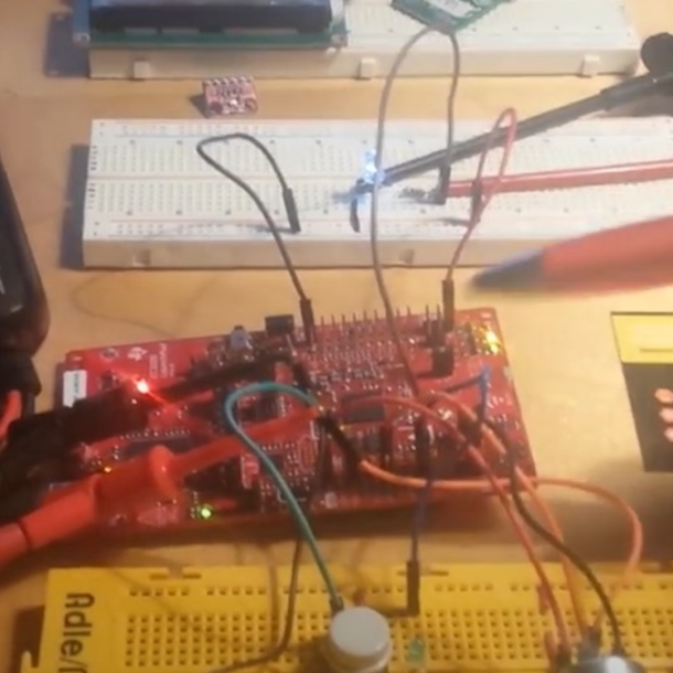
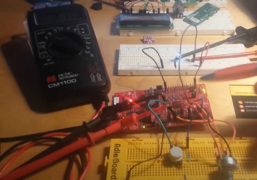
Now, from this setup, we will focus on the red pcb, a launchpad for the Texas Instruments CC3220 MCU. The firmware that I have developed is already installed and running.
What we have here, in this stage directly on the lcd of a multimeter. This multimeter is connected to a Pulse Width Modulated Analog output to which also an LED is connected.
Watch the Video
Since our Analog input is converted to a digital value, we will have to calibrate it. Also the conversion from the digital value read will have to be adjusted so that a Pulse Width Modulation can reproduce the initial voltage. We will look latter to the graphics and related analysis to understand it better.
The architecture is the following: a Real Time operating System, a Firmware running two threads, one for reading and one for writing, a callback for the calibration push button and a General Purpose IO to turn on the calibration LCD. Instead of a temperature sensor we will use a variable resistor and calibrate the readings. We will measure the Voltage in, the ADC value and the Voltage out for a given pulse width.
Let’s have a look at it and to what happens without a calibration and adjustment:
At this side of the board we have the variable resistor and a push button to enable the calibration. I’ll push it latter.
At the other side I have an LED that lights depending on the PWM and also a multimeter that measure the Voltage out.
We can see that the voltage at the output is not the same that the voltage at the input. Our output LED does not light in accordance to the measured temperature and most important, we could not know the temperature read with a termistor (or NTC resistance).
Before going into the mathematics I will push the calibration button and see how the reading at the input and the output are the same for all the range.
Movie